Get a Grip: How Rebar Splice Couplers Keep Concrete Strong
Why the Threaded Rebar Coupler Is Replacing Traditional Splicing on Tough Projects
A threaded rebar coupler is a short steel sleeve with internal threads that mechanically joins two reinforcing bars end-to-end — no concrete bond needed, no overlapping bars, no lap calculations.
Quick answer: What is a threaded rebar coupler?
- It is a steel sleeve that screws onto the threaded ends of two rebar sections
- It transfers load directly from bar to bar through thread engagement
- It exceeds 125% of the yield strength of ASTM A615 Grade 60 rebar
- It is approved under ACI 318, Eurocode 2, AASHTO, and IBC
- It is available in sizes from #4 (12mm) to #18 (57mm)
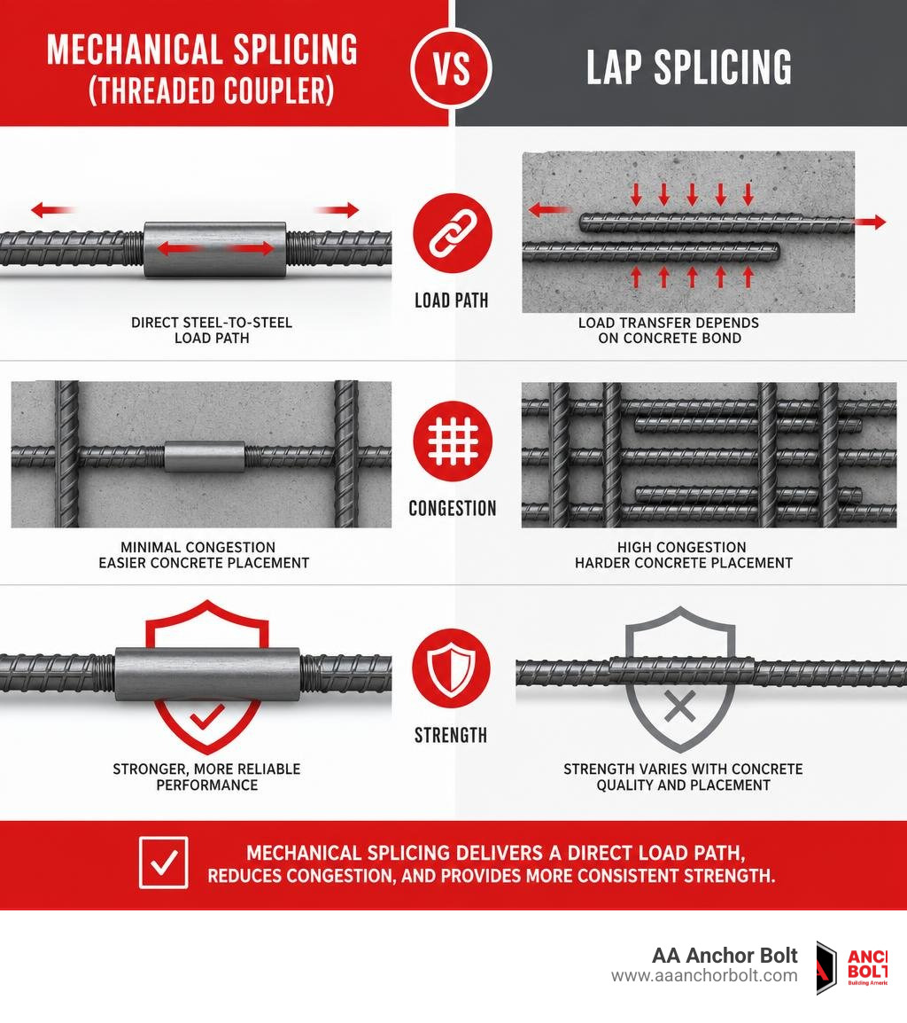
Traditional lap splices rely on the surrounding concrete to pass force from one bar to the next. That works — until it doesn’t. When concrete is poured in a congested rebar zone, air pockets and voids form easily, weakening the very joint the design depends on.
Threaded couplers cut through that problem. They create a direct, steel-to-steel load path that doesn’t depend on concrete quality at all. The result is a splice that is stronger, more compact, and more predictable — especially important for infrastructure projects with tight schedules and zero tolerance for rework.
What is a Threaded Rebar Coupler and How Does It Work?
To understand why a threaded rebar coupler is such a game-changer in modern concrete design, we have to look at how structural forces move through a building. In a traditional reinforced concrete structure, steel bars handle the tension, while concrete handles the compression. But rebar does not come in infinite lengths. When one bar ends, the structural load must be transferred to the next bar.
A mechanical coupler acts as a structural bridge. Instead of overlapping the steel and hoping the concrete holds them together, the coupler creates a continuous, high-strength steel connection. This ensures structural integrity by allowing direct force transmission in both tension and compression.
Whether the structure faces the steady pull of gravity or the sudden, violent reversals of an earthquake, the mechanical splice remains rock solid. This direct transfer is why modern building codes in 2026 increasingly specify mechanical couplers over old-fashioned lap splices for high-stress zones.
The Mechanics of a Threaded Rebar Coupler
At its core, a threaded rebar coupler works via precise thread engagement. The ends of the two reinforcing bars are threaded to match the internal threads of the coupler sleeve. When screwed together, the threads lock the bars in place, creating a continuous load path.
There are two primary threading designs used in the industry today:
- Parallel Threads: The rebar end is cut square and threaded with a uniform diameter. This design requires the coupler to be screwed along the entire length of the thread. To ensure that threading doesn’t reduce the cross-sectional area of the bar, manufacturers often use “upset forging” to enlarge the bar end before cutting the threads.
- Taper Threads: The threads are cut at a slight angle, narrowing toward the end of the bar. This allows for incredibly fast installation — you can spin the coupler on hand-tight for most of its length, and it locks securely with just a few turns of a wrench. This design minimizes the risk of cross-threading.
Both systems are engineered to achieve what is known as bar break performance. This means the mechanical connection is actually stronger than the rebar itself. Under extreme tensile testing, the parent bar will stretch and break outside of the coupler joint before the threads strip or the coupler fails.
For high-quality options, engineers often specify high-grade steel couplers that meet specific project demands and structural loads.
Threaded Rebar Coupler vs. Traditional Lap Splices
For decades, the standard way to join rebar was the lap splice. You simply overlap two bars by a calculated distance and tie them together with wire. But lap splices have major, built-in limitations.
First, they are entirely dependent on the concrete bond. If the concrete surrounding the lap zone cracks, degrades, or is poorly consolidated, the splice fails. Second, lap splices require a massive amount of extra steel.
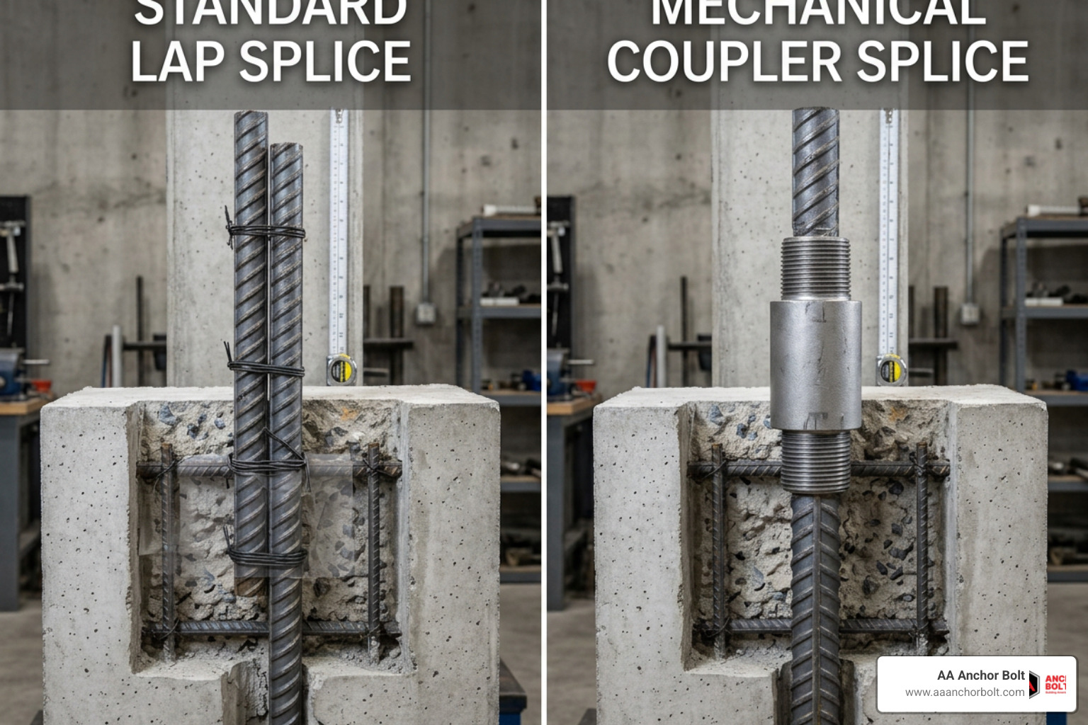
As structural loads increase, building codes stipulate that the steel-to-concrete ratio must remain under 8% to allow concrete to flow properly. When you overlap thick bars, you quickly exceed this limit, creating severe rebar congestion. This congestion blocks aggregate, leading to “rock pockets” and structural voids inside the formwork.
| Feature | Traditional Lap Splices | Threaded Rebar Coupler |
|---|---|---|
| Load Transfer Dependency | Relies entirely on concrete bond | Direct steel-to-steel transmission |
| Capacity | 100% of design capacity (highly variable) | 125% to 150% greater capacity than lap designs |
| Steel Congestion | High (doubles steel in the lap zone) | Minimal (slimmest profile possible) |
| Material Efficiency | Wasteful (requires feet of overlapping steel) | Highly efficient (zero wasted rebar) |
| Installation Speed | Slow; requires tedious lap calculations | Fast; simple screw-on assembly |
By eliminating the overlap, mechanical splices allow designers to achieve an ideal balance of steel and concrete, keeping the steel ratio well below the 8% limit and ensuring a clean, void-free concrete pour.
Types of Threaded Rebar Couplers and Their Applications
Not every concrete joint is the same, which is why there are several specialized types of threaded couplers designed for different structural scenarios. Selecting the right style depends on whether the bars can be rotated, if they are of different diameters, or if they need to attach to structural steel.
Standard and Reducing Couplers
Standard couplers are used when at least one of the reinforcing bars is free to rotate. You simply thread the coupler onto the fixed bar, butt the second bar against it, and rotate the second bar until the threads are fully engaged. These are incredibly common in columns, shear walls, and standard beam construction.
For projects requiring exceptional ease of use, standard taper-lock couplers are widely trusted industry options that use internal tapered female threads to allow fast, hand-tight installation.
Reducing (or transition) couplers are designed to connect bars of different diameters. For example, if a high-rise column transitions from heavy #11 bars on a lower floor to lighter #9 bars on an upper floor, a reducing coupler bridges the gap seamlessly without requiring complex formwork modifications.
Engineers can source various sizes and styles of specialized heavy-duty solutions to meet specific project requirements.
Positioning and Weldable Couplers for Complex Joints
What happens when neither bar can be rotated? This is a common challenge when connecting pre-fabricated rebar cages, curved bars, or bent structural elements.
In these cases, we use positioning couplers (sometimes called positional or adding-length thread connections). These systems utilize a longer thread on one bar. The coupler is screwed entirely onto this extended thread, the two bar ends are aligned, and the coupler is then backed off onto the second bar’s standard thread until it locks both sides together.
These systems are highly effective in complex field conditions where standard rotation is impossible.
Another critical specialty type is the weldable coupler (or weldable socket). These are made from low-carbon, weldable steel and are designed to be welded directly to structural steel plates, beams, or columns. This allows a seamless transition between structural steel framing and reinforced concrete elements.
For high-integrity international projects, specifying systems that comply with strict European standards ensures the weld behaves predictably under load. Additionally, high-precision manufacturing provides reliable options for specialized corrosion-resistant or cryogenic environments.
Engineering Specifications, Manufacturing, and Code Compliance
The reliability of a threaded rebar coupler depends entirely on the quality of its manufacturing and its compliance with strict engineering codes. Because these components are used in critical, load-bearing locations, they must undergo rigorous testing and quality control.
Structural Performance Under Static, Dynamic, and Seismic Loading
A structural splice must be able to withstand three types of forces:
- Static Loading: Constant, steady forces (such as the weight of the building itself). Threaded couplers easily handle these, consistently exceeding 125% of the specified yield strength ($f_y$) of ASTM A615 Grade 60 rebar.
- Dynamic Loading (Fatigue): Repetitive, cyclic forces over time (such as traffic crossing a bridge or machinery vibrating in a factory). Threaded couplers must pass high-cycle fatigue tests (often up to 2 million cycles) to ensure the threads do not wear down or slip.
- Seismic Loading (Low-Cycle Fatigue): Violent, reversing forces experienced during an earthquake. In seismic zones, couplers must meet “Type 2” mechanical splice requirements, meaning they must withstand severe plastic deformation and alternating tension and compression cycles without losing structural integrity.
To guarantee this level of performance in the field, leading manufacturers utilize advanced bar preparation methods like parallel roll threading. This process highlights how roll-threading preserves the steel’s grain structure to maximize tensile strength.
Building Code Approvals and Industry Standards
Before any mechanical splice can be installed on a job site, it must be approved by local and international building authorities. Key standards include:
- ACI 318 (American Concrete Institute): Defines Type 1 splices (125% yield strength) and Type 2 splices (full yield strength plus high-ductility seismic performance).
- AASHTO: Governs highway bridge design and construction.
- Eurocode 2 & ISO 15835: The international standards for reinforcing steel couplers.
- Caltrans (California Department of Transportation): Maintains some of the strictest seismic and structural approvals in the world. Engineers looking for verified products should consult the official Steel Reinforcing Couplers | Caltrans – CA.gov approved list to ensure code compliance.
Installation Best Practices and Quality Control
Even the best-engineered coupler will fail if it is installed incorrectly. Following proper field procedures is vital for structural safety.
- Thread Inspection and Cleaning: Before assembly, the threads on both the rebar and the inside of the coupler must be completely clean. Any dirt, rust, concrete splatter, or debris can prevent full thread engagement.
- Hand-Tight Assembly: Most modern couplers are designed to be spun on hand-tight initially. This prevents cross-threading. For taper-threaded systems, hand-tightening achieves a significant portion of the connection’s strength.
- Torque Verification: Depending on the system and the engineering requirements, a calibrated torque wrench may be used to tighten the connection to the manufacturer’s specified value. Typical torque values range from approximately 40 Nm (30 ft-lbs) for smaller 12mm (#4) bars up to 350 Nm (258 ft-lbs) for massive 40mm (#11 or #14) bars.
- Visual Inspection: Inspectors look for full thread engagement. Some systems feature “smart” bolts or visual indicators (like plastic caps or sheared-off bolt heads) to make inspection fast and foolproof.
Frequently Asked Questions about Threaded Rebar Couplers
Do threaded rebar couplers require a torque wrench for installation?
It depends on the system and the design specifications. Many modern parallel and taper-threaded couplers achieve full structural load capacity (bar break performance) simply by being screwed together until the bar ends butt tightly inside the sleeve. However, a torque wrench is often required when strict “slip control” or serviceability requirements are specified by the structural engineer to eliminate any minor movement in the joint under load.
How do threaded couplers prevent rebar congestion in concrete?
Traditional lap splices require overlapping two bars side-by-side, which doubles the width of the steel in that zone. In heavily reinforced columns or beams, this leaves very little space for concrete to flow between the bars. Threaded couplers align the bars end-to-end in a straight line, keeping the profile incredibly slim. This eliminates tight clusters of steel, allowing concrete to flow smoothly and preventing voids or “rock pockets.”
Can threaded couplers be used in seismic zones?
Yes, but they must be rated as Type 2 mechanical splices under building codes like ACI 318. Type 2 couplers are specifically engineered and tested to withstand the extreme, reversing cyclic loads of an earthquake, ensuring the connection remains ductile and does not fail even when the rebar stretches beyond its yield point.
Conclusion
In modern concrete construction, structural integrity and project efficiency are paramount. The threaded rebar coupler has proven to be a vital innovation, replacing outdated lap splices with a stronger, cleaner, and more reliable steel-to-steel connection. By eliminating rebar congestion and ensuring continuous load paths, these couplers help engineers build safer structures while keeping construction schedules on track.
At AA Anchor Bolt, we understand the demands of heavy construction. As a Michigan-based, family-owned manufacturer of custom anchor bolts and specialty fasteners, we are dedicated to supporting infrastructure projects across the United States. With nearly a million pounds of in-house steel and complete domestic production control at our Northville, MI facility, we deliver the fast turnaround times your project demands.
Ready to secure your next project with high-strength, American-made fasteners? Explore our custom manufacturing capabilities today.