U-Bolt for Data: Heavy Duty Mounts for Your Precious Tech
Why the Right U-Bolt for Data Infrastructure Is More Critical Than You Think
A U-bolt for data conduit support is a threaded, U-shaped fastener used to clamp and secure data conduits, cable trays, and fiber-optic runs to structural beams, overhead trusses, or pipe supports. Here is a quick overview of the most common types used in data infrastructure:
| U-Bolt Type | Best Use Case | Key Feature |
|---|---|---|
| PVC-Coated Malleable Iron | Outdoor or corrosive environments | 40 mil coating for corrosion resistance |
| Galvanized Steel | General conduit support | Cost-effective, weather-resistant |
| Stainless Steel | High-moisture or chemical exposure | Superior yield and ultimate capacity |
| High-Strength Steel | Heavy load, long-span applications | Highest load capacity available |
Data conduits are only as safe as the hardware holding them up. If a fastener fails, the cable runs fail — and that means downtime, damage, and costly repairs.
Most contractors treat U-bolts as a commodity. They grab whatever is on the shelf. But the loading direction, material grade, and thread condition of each U-bolt directly determines whether your conduit system holds or fails under real-world stress.
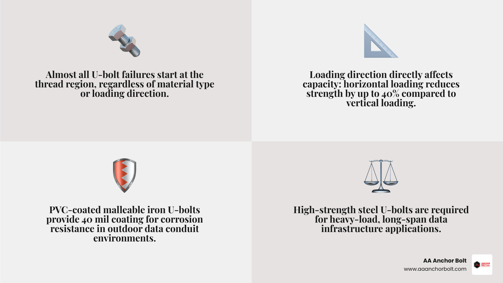
Research on structural U-bolt connections has shown that the thread region is the most vulnerable point — almost all failures start there, regardless of material type or loading direction. That is not a detail you want to discover on a job site.
I’m Pauline Horton, and in this guide I’ll walk you through exactly which U-bolts are built for data infrastructure work — so you can spec the right fastener the first time and keep your project on schedule.
U-bolt for data glossary:
Structural Demands of a U-Bolt for Data Conduit Support
When routing massive bundles of fiber-optic or copper data lines through industrial complexes, data centers, or across outdoor infrastructure, mechanical stability is non-negotiable. These cable pathways are often housed in heavy steel or PVC-coated rigid conduits that must traverse long spans, hang from overhead steel trusses, or cling to structural beams. Securing these runs requires a deep understanding of how a U-bolt for data performs under continuous physical stress.
Conduit routing is rarely a straightforward, static affair. Environmental vibrations, thermal expansion, wind loads on outdoor bridges, and the sheer dead weight of high-density cabling exert multi-directional forces on the supporting hardware. Standard off-the-shelf light-duty clamps can easily yield or slip under these conditions.
For highly corrosive environments or heavy-duty industrial facilities, specialized options like the UB2-G | U bolts | Kindorf | Wire & Cable Management | Electrical Distribution | Ecatalog | Ecatalog PVC-coated malleable iron U-bolt are utilized. Designed to support a 2-inch pipe or conduit run, this hardware features a nominal 40 mil (0.040 inches) PVC coating that shields the base metal from corrosive chemicals and moisture.
However, to ensure these critical fasteners fit your exact routing configurations, standard sizes are not always enough. Fabricating custom dimensions requires specialized bending methods. If you are interested in the physical mechanics behind how these fasteners are shaped, you can read our guide on How to Bend a U-Bolt in 5 Simple Steps to understand how we maintain structural integrity during the manufacturing process.
Load Capacities and Failure Modes under Multi-Directional Stress
To design reliable support structures, engineers must look beyond simple static pull tests and analyze how U-bolt assemblies respond to multi-directional forces. Extensive structural research on 3/4-inch diameter U-bolt connections reveals that load capacity varies drastically depending on whether the force is applied horizontally (parallel to the support member) or vertically (perpendicular to the support member).
The performance differences between connection designs are stark:
- Type-A Connections (Standard Two-Sided Clamping): Under horizontal loading, a Type-A U-bolt connection achieved an ultimate capacity of 38 kips. However, when subjected to vertical loading, its ultimate capacity fell significantly to 24 kips.
- Type-B Connections (Offset or Single-Sided Bracing): A Type-B configuration demonstrated an ultimate capacity of 35 kips under horizontal loading.
The physical orientation of the load changes how the stress distributes through the fastener. Under vertical loads, the U-bolt is subjected to direct tension and bending across its curved crown, whereas horizontal loads distribute stress more evenly along the shanks.
Across all material types, configurations, and loading directions, structural testing consistently identifies the thread region as the most vulnerable location. Because the cutting or rolling of threads reduces the net cross-sectional area of the bolt, it creates severe stress concentration points. Consequently, the vast majority of mechanical failures initiate in this thread region, emphasizing the need for high-quality thread manufacturing and precise torque specifications during installation.
Material Properties and Yield Capacity of a U-Bolt for Data Systems
The metallurgical composition of your fasteners directly dictates their performance threshold. When selecting a U-bolt for data conduit systems, engineers must balance yield strength (the point where permanent deformation begins) and ultimate tensile strength (the point of complete physical failure).
Consider the dramatic performance gap between standard structural steel and high-strength alloys under a 0° (horizontal) loading angle:
- Standard Galvanized Steel: A Type-A U-bolt connection fabricated from standard galvanized steel (with a yield strength $fy = 36$ ksi and ultimate strength $fu = 58$ ksi) yielded at less than 1极0 kip under 0° loading. This makes standard carbon steel highly susceptible to slipping or deforming under sustained structural loads.
- Standard Stainless Steel: Upgrading to a Type-B stainless steel U-bolt (with a yield strength $fy = 30$ ksi and ultimate strength $fu = 75$ ksi) under 0° loading raised the yield capacity to 8.5 kips. The superior ductility of stainless steel allows it to absorb significantly more energy before permanent deformation occurs.
- High-Strength Galvanized Steel: A Type-A connection using high-strength galvanized steel ($fy = 92$ ksi, $fu = 120$ ksi) under 90° loading achieved an ultimate capacity of 39 kips.
- High-Strength Stainless Steel: A Type-B connection utilizing high-strength stainless steel ($fy = 100$ ksi, $fu = 125$ ksi) under 0° loading achieved an ultimate capacity of 48 kips.
By matching the steel grade to the calculated mechanical demands of the routing run, you prevent premature sagging of the conduit pathways, protecting the delicate glass fibers inside from micro-bending losses.
Engineering Considerations for Large-Scale Data Infrastructure
Designing the physical pathways for massive data centers or industrial plants in 2026 requires rigorous structural engineering. Standard electrical hangers are insufficient when routing heavy, multi-tiered conduit runs over long spans. Engineers must treat these conduit supports as integrated structural systems, utilizing advanced tools like interaction diagrams to calculate safe load limits under combined loading conditions.
When a U-bolt is clamped around a conduit, it experiences tension from pre-torqueing, vertical shear from the weight of the cables, and horizontal forces from thermal movement or external vibrations. To prevent catastrophic failure, engineers use interaction diagrams to plot the relationship between axial tension and shear forces. If the combined force vectors fall outside the safe boundary curve of the diagram, the connection is at risk of yielding.
| U-Bolt Material Grade | Yield Strength ($f_y$) | Ultimate Strength ($f_u$) | Loading Angle | Yield Capacity | Ultimate Capacity |
|---|---|---|---|---|---|
| Galvanized Steel | 36 ksi | 58 ksi | 0° (Horizontal) | < 1.0 kip | N/A |
| Stainless Steel | 30 ksi | 75 ksi | 0° (Horizontal) | 8.5 kips | N/A |
| High-Strength Galvanized | 92 ksi | 120 ksi | 90° (Vertical) | N/A | 39.0 kips |
| High-Strength Stainless | 100 ksi | 125 ksi | 0° (Horizontal) | N/A | 48.0 kips |
Designing a U-Bolt for Data Centers and Overhead Trusses
In modern data centers, cabling is frequently routed overhead along structural steel trusses to keep the floor space clear for server racks and cooling systems. As spans between truss supports increase, the mechanical demands on the mounting hardware multiply.
Key engineering considerations for overhead truss installations include:
- Size Effects: Larger diameter U-bolts do not scale linearly in strength. As the diameter of the bolt increases, the volume of material subject to maximum stress increases, which can influence fatigue life and susceptibility to micro-defects.
- Fatigue Performance: In industrial environments, overhead structures are subjected to continuous low-amplitude cyclic loading from HVAC equipment, generators, and manufacturing machinery. Over time, these micro-vibrations propagate micro-cracks starting in the high-stress thread region of the U-bolt.
- Preload Calibration: Achieving the correct torque during installation is critical. Under-tightening allows the conduit to slip, causing friction wear, while over-tightening introduces excessive tensile stress into the thread region, accelerating fatigue failure.
Ongoing research into structural fasteners continues to focus on improving the fatigue life of threaded connections through advanced thread-rolling techniques and specialized coatings. At AA Anchor Bolt, we monitor these technical advancements closely. Our Services and Manufacturing Capabilities allow us to produce custom-engineered fasteners that meet the strict tolerances required for high-vibration industrial environments.
Protecting High-Performance Data and Power Cables
Securing the conduit is only half the battle; the physical and electrical characteristics of the cables running inside must also be protected. High-speed data cables are highly sensitive to physical deformation, tight bends, and electromagnetic interference (EMI). If a U-bolt is over-tightened directly onto a cable bundle or a thin-walled conduit, it can crush the internal geometry of the conductors, leading to signal degradation or physical shorts.
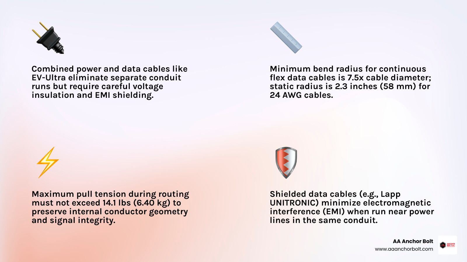
For high-flexibility, high-motion industrial applications, cables like the DATA 700 TPi CD | Double-shielded continuous bending hi-flex PUR data cables are designed to withstand up to 7 million motion cycles. To prevent internal friction and wear during continuous movement, these cables feature a minimum bending radius of 7.5 times the cable diameter when moved.
Similarly, continuous flex data cables such as those detailed in the 86207 Technical Data Sheet | XTRAGUARD FLEX Continuous Flex Data Cable Specifications require careful physical management. This 24 AWG 7-conductor cable has a nominal capacitance of 21.2 pF/ft (69.6 pF/m) and a nominal inductance of 0.19 µH/ft (0.62 µH/m). To preserve these electrical properties and prevent signal attenuation, installers must maintain a minimum stationary bend radius of 2.3 inches (58 mm) and ensure that maximum pull tension does not exceed 14.1 lbs (6.40 kg) during routing.
Combined Power and Data Cable Specifications
A growing trend in modern infrastructure is the consolidation of power delivery and data transmission within a single cable assembly, such as EV-Ultra cables used for smart electric vehicle charging stations. This approach eliminates the need for separate conduit runs but introduces complex electrical and mechanical challenges.
According to technical specifications for EV-Ultra combined cables:
- 4.0mm² Conductor: Features a maximum current rating of 45 A and a voltage drop of 12 mV/A/m.
- 6.0mm² Conductor: Features a maximum current rating of 58 A and a voltage drop of 7.9 mV/A/m.
- Environmental Limits: These cables are rated for a minimum operating temperature of -15˚C up to a maximum of 90°C.
When routing these combined cables, maintaining mechanical protection is critical. Because they carry both low-voltage data signals and high-current power, any physical damage from a crushed conduit or an over-tightened U-bolt could result in a dangerous short circuit, carrying standard mains voltage directly into the sensitive data logging equipment.
Industrial Communication and Shielded Data Cables
In heavy industrial automation, communications often rely on specialized fieldbus protocols. Cables like the 2170820 | Lapp UNITRONIC BUS PB FC Data Cable, 2 Cores, 0.64 mm² CSA, Screened, 100 m, Purple Polyvinyl Chloride Sheath | RS are the backbone of Profibus (PB) networks.
This dual-core, shielded cable features a 250V voltage rating, an 8mm outside diameter, and a 0.64 mm² cross-sectional area. The polyolefin internal insulation offers superior resistance to chemical exposure, while the double-shielded design blocks electromagnetic interference from surrounding heavy machinery.
When mounting conduits carrying these sensitive communication lines, using high-quality support hardware prevents physical sagging and protects the shielding from mechanical wear. Any physical distortion of the cable’s internal geometry will directly alter its nominal impedance, leading to signal reflections and communication dropouts across the entire automation network.
Frequently Asked Questions about Data Conduit Support
What is the most vulnerable failure point on a U-bolt under load?
The thread region is mathematically and physically the most vulnerable point on any U-bolt. When threads are cut or rolled into a steel shank, the cross-sectional area of the metal is reduced, creating a natural point of stress concentration. Under structural loading, mechanical stresses accumulate in the roots of the threads.
Physical testing shows that almost all structural failures initiate in this thread region, regardless of whether the bolt is made of carbon steel, galvanized steel, or high-strength stainless steel. To mitigate this risk, engineers must specify precise installation torques and avoid over-tightening, which introduces excessive pre-tension into the threads.
Can you run power and data in a single conduit secured by U-bolts?
Yes, but only under strict regulatory conditions. According to standard electrical codes (such as BS 7671 in the UK or the NEC in the United States), low-voltage data lines (Voltage Band I) and low-voltage power lines (Voltage Band II) can only share a conduit or wiring system if every conductor in the run is insulated to the highest voltage present.
Additionally, you must use screened, twisted-pair data cables to prevent electromagnetic interference (EMI) from the power lines from corrupting the data signals. The conduit itself must be securely supported by heavy-duty fasteners to prevent sag or mechanical stress on the internal cables.
How do loading directions affect the ultimate capacity of U-bolt connections?
Loading direction has a massive impact on the ultimate capacity of a U-bolt assembly. When a U-bolt is loaded horizontally (0° loading, parallel to the mounting member), the stress is distributed more evenly down both shanks, allowing the connection to achieve higher capacities (e.g., 38 kips for a Type-A connection).
However, when loaded vertically (90° loading, perpendicular to the mounting member), the force acts directly against the curved crown of the U-bolt, inducing severe bending moments. This reduces the ultimate capacity significantly (down to 24 kips for the same Type-A connection). Engineers must always consult multi-directional interaction diagrams when designing support structures subjected to combined vertical and horizontal forces.
Conclusion
Securing modern data infrastructure requires hardware that can withstand severe mechanical and environmental demands. A U-bolt for data conduit systems is not a minor accessory; it is a critical structural component that ensures the physical integrity of your fiber-optic and electrical pathways. From managing multi-directional stress on overhead trusses to protecting high-flexibility communication cables from mechanical crushing, selecting the right fastener grade and configuration is paramount.
At AA Anchor Bolt, we manufacture custom structural fasteners designed to meet these exact engineering specifications. Operating out of our Northville, Michigan facility, we maintain complete domestic production control. With nearly a million pounds of in-house steel, we deliver rapid turnarounds on custom orders without compromising on quality or material traceability.
If you need custom-manufactured, high-strength U-bolts, anchor bolts, or specialty fasteners tailored to your data infrastructure project, explore our complete line of domestic Products or contact our engineering team today to discuss your project specifications.