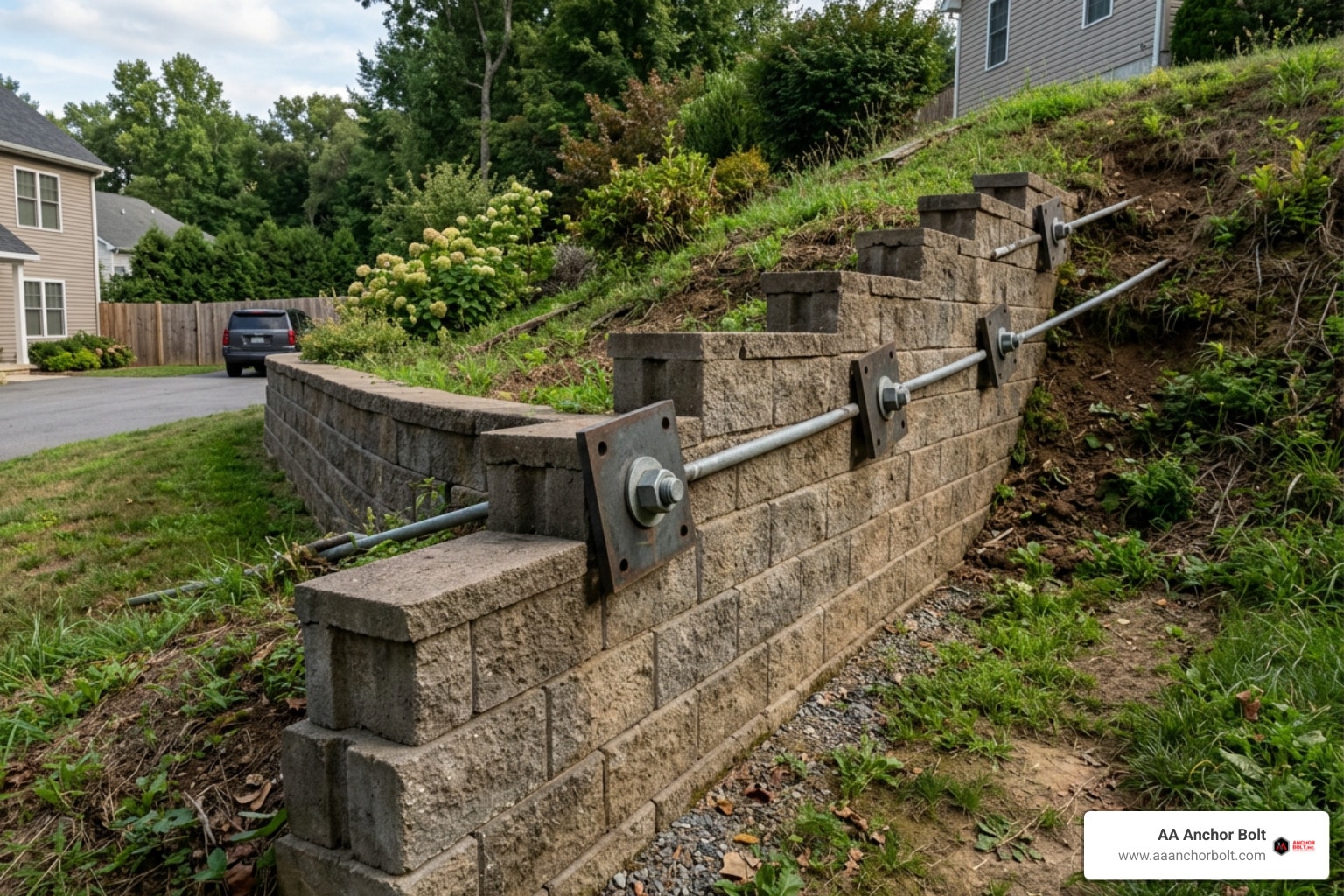
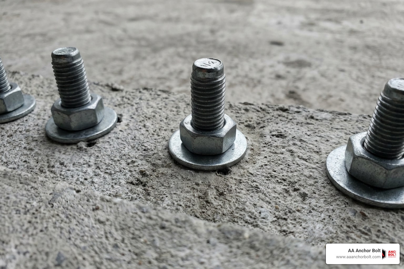
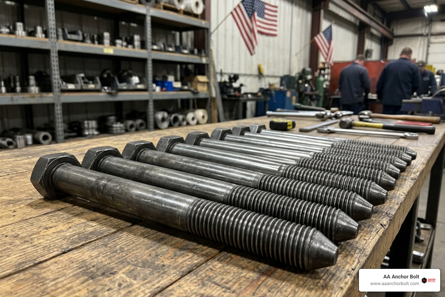
Set It and Forget It with Heavy-Duty Cast-in-Place Concrete Anchors
Why Cast-in-Place Anchors Deliver Reliable Heavy-Duty Connections
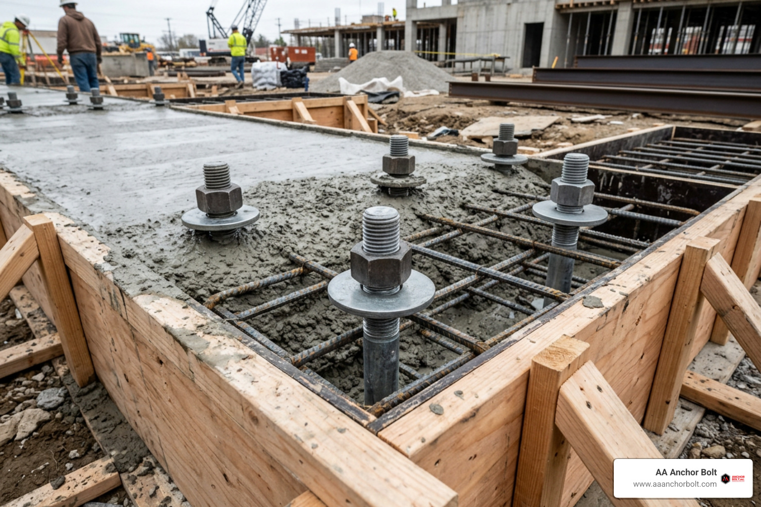
Cast-in-place anchors for concrete are set in position before the pour, so the hardened concrete forms around the anchor and its head, hook, or plate. This makes them a strong choice for foundations, equipment bases, structural steel columns, and other heavy-duty connections where tension and shear loads matter.
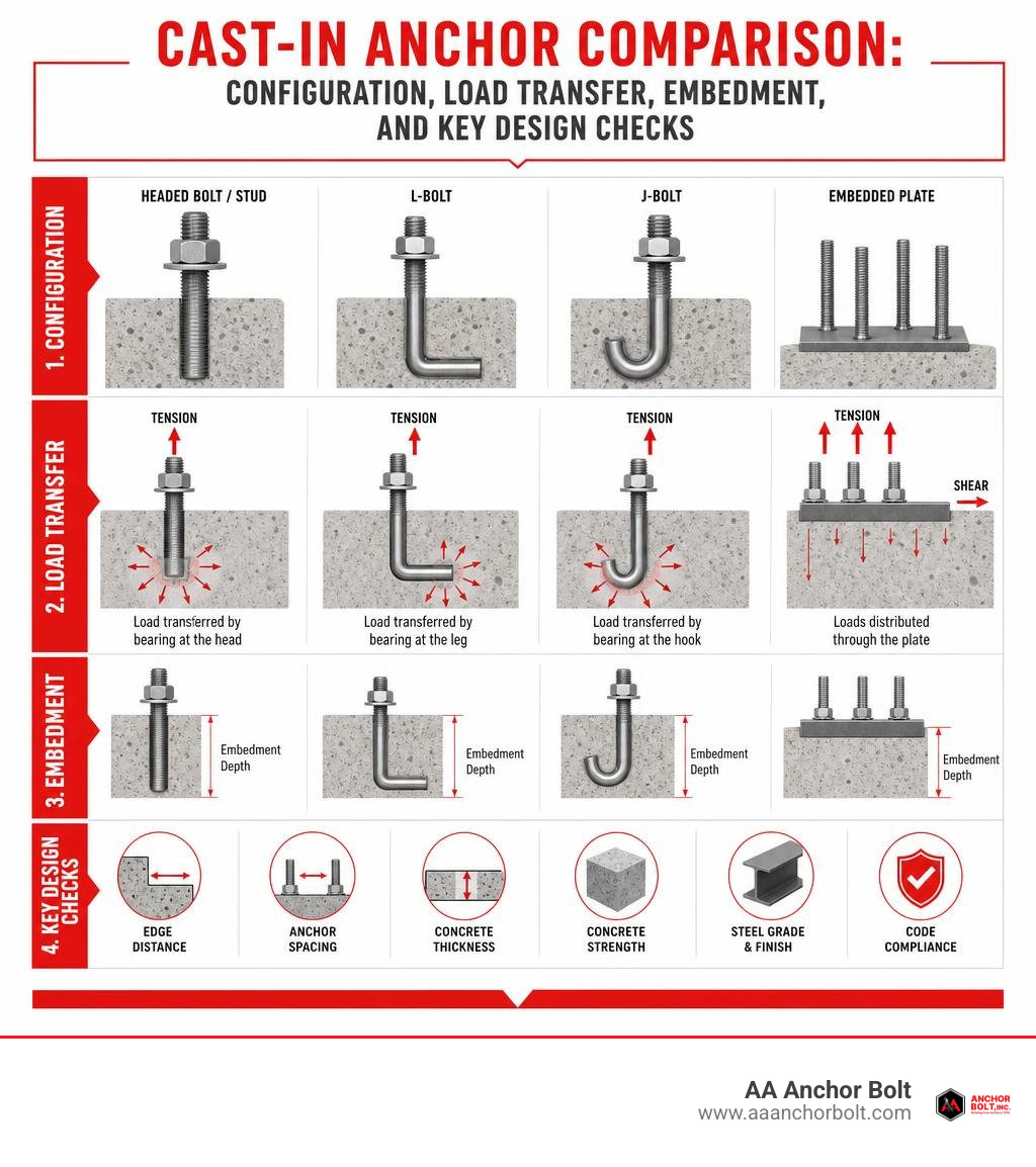
For most projects, compare anchor options based on:
- Anchor style: headed bolts and studs, L-bolts, J-bolts, or embedded plates
- Effective embedment depth: deeper embedment generally provides more concrete breakout resistance
- Concrete thickness, edge distance, and spacing: thin slabs and close edges can limit capacity
- Steel grade and finish: select the needed strength and corrosion protection before fabrication
Unlike post-installed anchors, cast-in anchors do not rely on drilling, expansion, or adhesive bond after the concrete has cured. A properly detailed anchor transfers tension through bearing at its embedded head or other anchorage feature, while surrounding concrete resists breakout and shear forces.
I am Pauline Horton, and next we will look at the anchor types, design limits, and practical details that help contractors choose the right embedded connection without slowing down the pour schedule.
Understanding Cast-in-Place Anchors for Concrete Foundations
When planning a commercial, industrial, or infrastructure foundation, selecting the right anchor strategy sets the foundation for the entire structural frame. Placing an anchor assembly directly into the formwork before pouring creates a monolithic connection with the curing concrete. Because the wet mix flows directly around the anchor shank, bearing head, or embedded plate, the hardened concrete bonds naturally with the steel.
This monolithic relationship allows the anchor to distribute massive structural loads directly into the concrete foundation. Unlike retrofitted anchoring methods that force you to drill into cured slabs, pre-pour anchor placement preserves the integrity of the concrete surrounding the connection.
| Anchor Configuration | Primary Load Transfer Mechanism | Typical Embedment Depth ($h_{ef}$) | Common Structural Applications |
|---|---|---|---|
| Headed Bolt (Hex / Heavy Hex) | Direct mechanical bearing on bolt head | $4da$ to $25da$ (typically $\ge 2\text{-}3/4\text{ in.}$) | Structural column base plates, crane rails, heavy equipment |
| Bent Bar (L-Bolt / J-Bolt) | Mechanical bearing along inner bend surface | $6da$ to $12da$ | Light poles, sign structures, light framing sill plates |
| Welded Stud (Headed Shear Stud) | Direct bearing on stud head via welded plate | $3da$ to $10da$ | Composite beam construction, embedded steel bearing plates |
| Anchor Rod with Bearing Plate | High-surface-area bearing on embedded plate | Custom (engineered for breakout cone) | Seismic bridge bents, high-moment towers, industrial presses |
ACI 318-19 Chapter 17 Anchor Classifications
Under the American Concrete Institute structural standard (ACI 318-19 Chapter 17), concrete anchors fall into distinct categories that dictate how we calculate their capacity. Cast-in anchors include headed studs, headed bolts, and hooked bolts placed in the formwork before the pour. Post-installed anchors encompass mechanical systems (expansion, screw, and undercut anchors) and adhesive systems installed into hardened concrete.
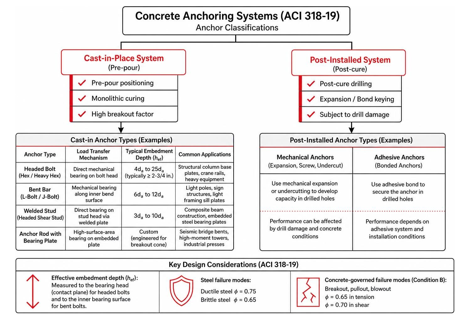
A key variable in these design provisions is effective embedment depth ($h_{ef}$). For a cast-in headed bolt, $h_{ef}$ is measured from the concrete surface down to the contact plane of the bearing head. For bent bolts, it extends to the inner bearing surface of the hook.
ACI 318-19 also distinguishes between ductile and brittle steel failure modes. To design a ductile anchor connection, the steel element must stretch significantly before rupturing, giving visible warning of overstress. Under ACI 318-19, ductile cast-in anchors receive a favorable strength reduction factor ($\phi = 0.75$) for steel tension, whereas brittle steel elements require a stricter reduction ($\phi = 0.65$). For concrete-governed failure modes (breakout, pullout, blowout) without supplementary reinforcement (Condition B), the standard assigns $\phi = 0.65$ in tension and $\phi = 0.70$ in shear. For a broader engineering comparison, consult our concrete fastener guide for heavy duty anchoring.
Embedment Integrity and Mechanical Keying
The mechanical advantage of a pre-set anchor comes from aggregate interlock. When concrete is placed monolithically, paste and coarse aggregate settle tightly against every surface of the anchor head and shank. This complete contact eliminates the micro-annular voids often seen around drilled holes.
By contrast, post-installed mechanical anchors must create internal radial expansion forces to grip the sidewalls of a drilled hole. As detailed in the standard qualification standards (such as ACI 355.2-24), expansion anchors exert continuous outward pressure on the concrete. Cast-in headed anchors remain relaxed in the cured matrix, generating internal stress only when an external tension or shear load is applied.
Heavy-Duty Cast-in Anchor Configurations and Material Grades
Industrial and civil engineering designs demand steel tailored to specific yield strengths, ductilities, and environmental exposures. At AA Anchor Bolt, we manufacture domestic cast-in anchors from our Michigan facility to match exact project specifications.
ASTM F1554 Headed Bolts and Studs
The standard specification for structural anchoring is ASTM F1554. It covers anchor bolts designed for structural support across three distinct yield strengths:
- F1554 Grade 36: Mild carbon steel with a minimum yield strength of 36 ksi (tensile strength 58–80 ksi). This grade offers excellent ductility, is easy to weld, and serves as an industry workhorse for standard building columns.
- F1554 Grade 55: A medium-strength, low-alloy steel providing a 55 ksi minimum yield strength (tensile strength 75–95 ksi). Grade 55 can be ordered with weldability supplement S1, making it a versatile option for high-wind framing and transportation structures.
- F1554 Grade 105: A high-strength, heat-treated alloy steel delivering a minimum yield strength of 105 ksi (tensile strength 125–150 ksi). It is selected for high-load applications like tall towers, heavy industrial bases, and seismic tie-downs where space constraints prevent large bolt patterns.
To learn more about choosing between these materials, read our guide on demystifying ASTM F1554 steel grades or review our dedicated F1554 anchor bolt specifications.
Bent Bar and Custom Embedded Anchors
While headed studs and bolts transfer loads via their wide heads, bent bar anchors (L-bolts and J-bolts) rely on their hooked profiles.
- L-Bolts (90-degree bends): Commonly used for lightweight anchorage, such as securing light poles, sign posts, and residential sill plates. The leg provides mechanical pullout resistance, though ACI 318 limits their allowable tension compared to headed fasteners due to potential straightening under high loads.
- J-Bolts: Feature a rounded hook profile that distributes bearing across an arc, offering anchor placement flexibility around dense rebar cages.
To prevent the anchor assembly from pulling through the foundation base plate during tensioning, engineers pair these bolts with heavy hex nuts. For configuration advice, see our recommendations on heavy hex nuts selection. When a project requires unique bend radiuses, oversized lengths, or welded anchor plate assemblies, our team provides tailored solutions through our custom manufacturing capabilities.
Engineering Design Parameters and Critical Failure Modes
Designing a cast-in anchoring system requires checking every potential failure mode under ACI 318-19 Chapter 17. The design strength of the connection is governed by the lowest value among these checks.

Tensile Breakout and Anchor Head Bearing Mechanics
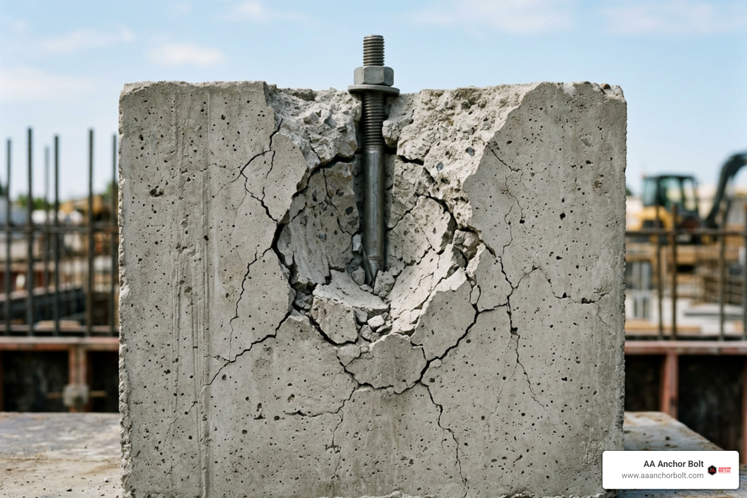
When an anchor is pulled in tension, the primary concrete limit state is concrete breakout. Under the Concrete Capacity Design (CCD) method, the breakout surface forms an idealized 35-degree failure prism (approximated as a cone) expanding outward from the bearing head to the concrete surface.
The basic nominal concrete breakout strength of a single cast-in anchor in tension ($N_b$) is calculated as:
$$Nb = kc \lambda_a \sqrt{f’c} \, h{ef}^{1.5}$$
Where:
- $k_c$ is the concrete effectiveness factor.
- $\lambda_a$ is the lightweight concrete modification factor (1.0 for normalweight concrete).
- $f’_c$ is the specified concrete compressive strength in psi.
- $h_{ef}$ is the effective embedment depth in inches.
The value of $k_c$ highlights the structural efficiency of cast-in anchors:
- For uncracked concrete, $k_{uncr} = 24$ (in-lb units) or $10$ (SI units).
- For cracked concrete, $k_{cr} = 17$ (in-lb units) or $7.1$ (SI units).
For instance, consider a single 3/4-inch diameter cast-in headed anchor with an effective embedment depth of 3-1/2 inches set in uncracked 2,500 psi normalweight concrete. The nominal breakout capacity is:
$$N_b = 24 \times 1.0 \times \sqrt{2500} \times (3.5)^{1.5} = 24 \times 50 \times 6.5479 \approx 7,857 \text{ lb}$$
Applying the Condition B strength reduction factor ($\phi = 0.65$) yields a design tensile strength ($\phi N_b$) of roughly $5,107\text{ lb}$ ($22.72\text{ kN}$).
In addition to breakout, engineers must verify the head bearing stress to prevent pullout failure. Headed bolts use a heavy hex head or bearing washer so that compressive stresses against the concrete remain well below allowable bearing limits ($8 f’_c$ per ACI 318 provisions).
Edge Distance, Spacing, and Thin Slab Design for Cast-in-Place Anchors for Concrete
Edge distance ($c$) and center-to-center anchor spacing ($s$) heavily influence structural capacity:
- Critical Edge Distance ($1.5 h_{ef}$): If an anchor is placed closer than $1.5 h_{ef}$ to an edge, its breakout cone is truncated, reducing tensile capacity.
- Minimum Edge Distance ($0.5 h_{ef}$): Cast-in headed anchors require a minimum edge distance to prevent lateral bursting (side-face blowout) during tensioning. When $h_{ef} > 11\text{ in.}$ and edge distance $c < 0.4 h_{ef}$, side-face blowout must be checked per ACI 318-19 Section 17.6.4.
- Thin Slab Challenges (3 to 4 inches): Thin precast or cast-in-place slabs present geometric limits. Because minimum embedment for a 1/2-inch headed stud is around 2-3/4 inches and a 5/8-inch stud requires at least 3-1/8 inches, a 3-inch slab leaves negligible concrete cover. In these shallow members, the full breakout cone cannot develop, making supplementary reinforcement necessary.
For deep-dive tables on edge distances and minimum geometries, review our complete guide to F1554 anchor bolt specs.
Gray-Area Connections and Precast Hole Considerations
A common scenario in precast construction involves forming a smooth void in a precast panel using a removable sleeve, allowing a bolt to be inserted on-site. Structural engineers often ask: Does this connection qualify as a cast-in or post-installed anchor under ACI 318?
Evaluating Pre-Formed Holes and Non-Standard Cast-in-Place Anchors for Concrete
Technically, a loose bolt inserted through a smooth pre-formed hole fits neither standard definition:
- It is not a cast-in anchor because concrete was not poured directly against the bolt head to create a monolithic mechanical interlock.
- It is not a post-installed anchor because it was not qualified under ACI 355.2 (mechanical) or ACI 355.4 (adhesive) standards, and no drilling occurred.
Smooth-sided holes lack the microscopic roughness produced by hammer drilling. If an adhesive is injected without mechanically roughening the sleeve surface, bond performance drops significantly. If left unbonded as a loose through-bolt, the connection transfers load purely by bearing at the washer plate on the far side of the slab. Engineers must calculate this configuration using baseline mechanics: washer bending, concrete bearing beneath the plate, and punching shear through the slab thickness.
Qualification Testing and Engineering Judgment Under ACI and ASTM Standards
When connections fall outside the standard formulas of ACI 318 Chapter 17, engineering judgment must be supported by empirical testing. Under ASTM E488 (Standard Test Methods for Strength of Anchors in Concrete Elements), assemblies are pulled to failure to establish characteristic capacities.
Statistical evaluations determine the 5% fractile characteristic capacity with 90% confidence. Working with a domestic manufacturer that understands these standards helps ensure your custom anchor components comply with job specifications. Learn more in our guide on finding reliable anchor bolt manufacturers.
Frequently Asked Questions about Cast-in Concrete Anchors
How do heavy-duty cast-in headed anchors transfer tensile loads into concrete?
Cast-in headed anchors transfer tensile loads primarily through direct mechanical bearing of the embedded bolt head or bearing plate against the surrounding concrete. When tension is applied to the bolt shank, compressive bearing stresses radiate outward from the head into the cured concrete, activating a 35-degree breakout cone that distributes the load deep into the foundation.
How does concrete cracking impact the breakout strength factor for cast-in bolts?
Concrete cracking reduces the breakout strength factor because tension cracks interrupt the concrete matrix along the failure cone. In ACI 318-19 Table 17.6.2.2, the effectiveness factor for uncracked concrete ($k_{uncr}$) is 24, whereas for cracked concrete ($k_{cr}$) it is 17. This represents an approximate 29% reduction in basic concrete breakout capacity when cracks wider than 0.012 inches are anticipated.
When must an anchor installed in a precast void undergo qualification testing rather than standard ACI 318 calculation?
An anchor installed in a pre-formed void must undergo qualification testing when the geometry, hole roughness, or load-transfer mechanism does not meet the prescriptive criteria of ACI 318-19 Chapter 17. If a bolt rests loosely in a smooth pre-formed sleeve or uses an unapproved adhesive without mechanical aggregate interlock, standard breakout formulas do not apply, requiring empirical load testing per ASTM E488 or baseline punching shear calculations.
Conclusion
Cast-in anchors deliver high tensile and shear capacities for heavy structural applications. By taking advantage of monolithic concrete placement, heavy hex bearing surfaces, and proven ASTM F1554 steel grades, they provide solid anchoring performance across major infrastructure projects.
At AA Anchor Bolt, we manufacture custom anchor bolts and specialty fasteners backed by nearly a million pounds of domestic steel inventory. Whether your job calls for high-strength F1554 Grade 105 headed assemblies, custom-bent J-bolts, or fabricated embedment plates, our Northville, Michigan facility delivers quick turnaround times with strict quality control.
Explore our complete line of heavy-duty cast-in anchor bolt products to secure your next concrete foundation pour.