The Ultimate Guide to Choosing a U-Bolt Bending Machine
Choose a U-Bolt Bending Machine That Matches Your Production Needs
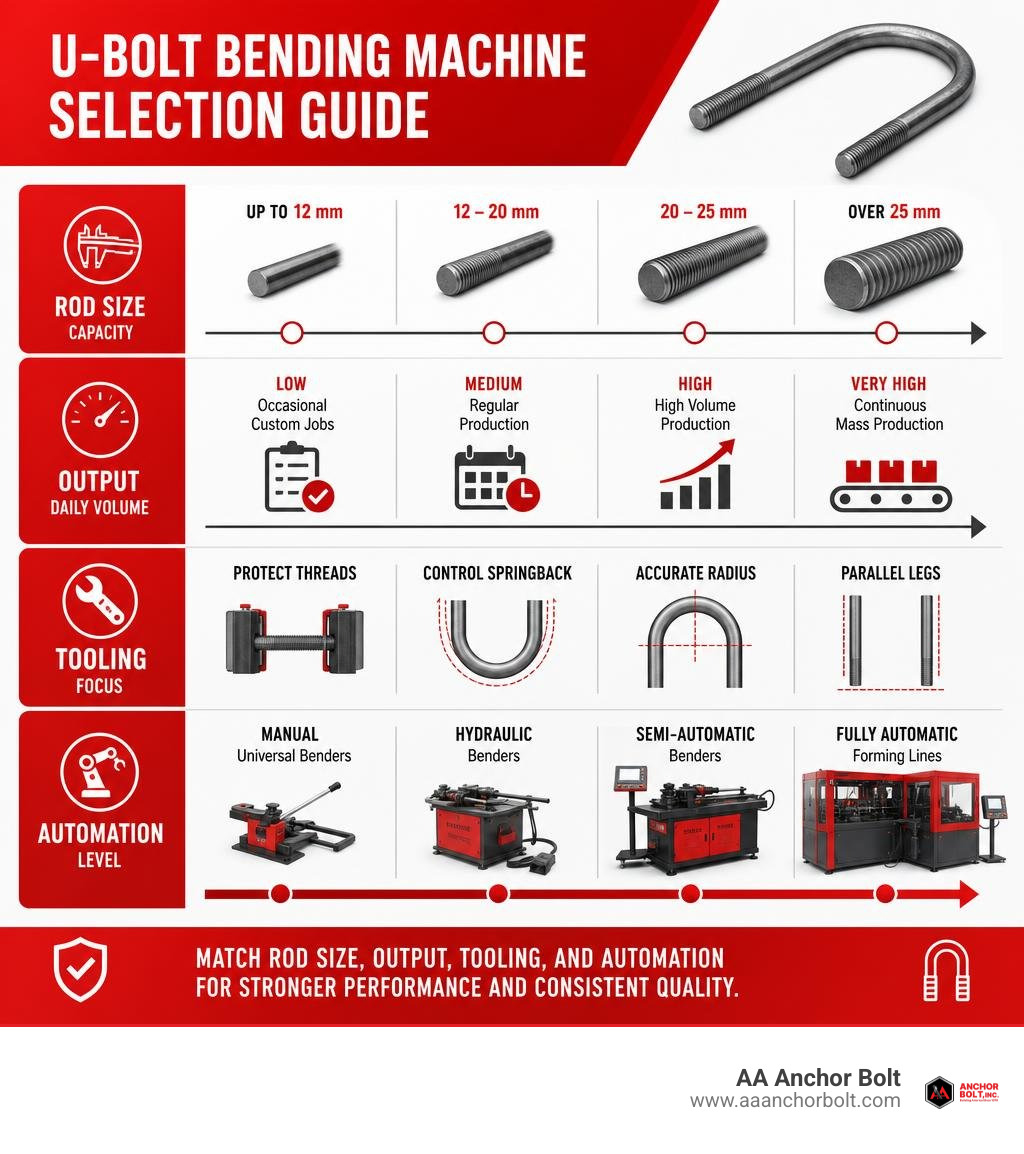
A U-bolt bending machine forms steel rod or pre-threaded bar into accurate U shapes for pipe supports, axle clamps, structural anchors, and other heavy-duty fastening jobs. The right machine should match your largest rod diameter, required bend radius, daily output, and tolerance needs.
For tight infrastructure schedules, focus on these basics first:
- Manual or universal benders suit occasional, custom-size work.
- Hydraulic benders provide repeatable force for heavier rod, often around 20 to 25 mm capacity.
- Automatic forming lines make sense for high-volume production, where speed and consistent dimensions matter most.
- Choose tooling that protects threads, controls springback, and keeps both legs parallel.
A dedicated machine uses a forming die, controlled overbend, and secure workholding to make a consistent radius in a single bending cycle. That matters because a U-bolt that does not sit correctly on its mating surface can distort during tightening and lose clamping force.
I am Pauline Horton, and this guide will help you compare U-bolt bending equipment based on practical production, quality, and lead-time requirements.
Quick u bolt bending machine definitions:
Core Classifications of U-Bolt Bending Equipment
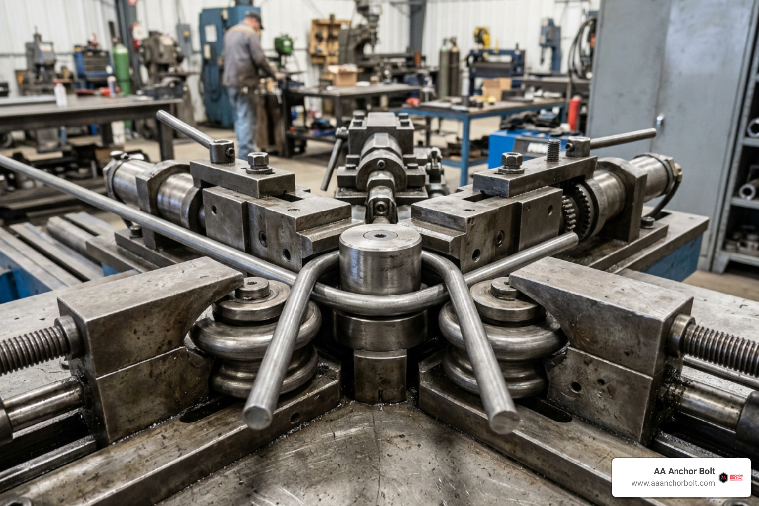
Industrial bolt bending machinery spans everything from manual shop benders to heavy hydraulic stations and high-throughput automated lines. Selecting the right setup comes down to your production volume, the bar diameters you bend, and the level of dimensional repeatability your applications demand.
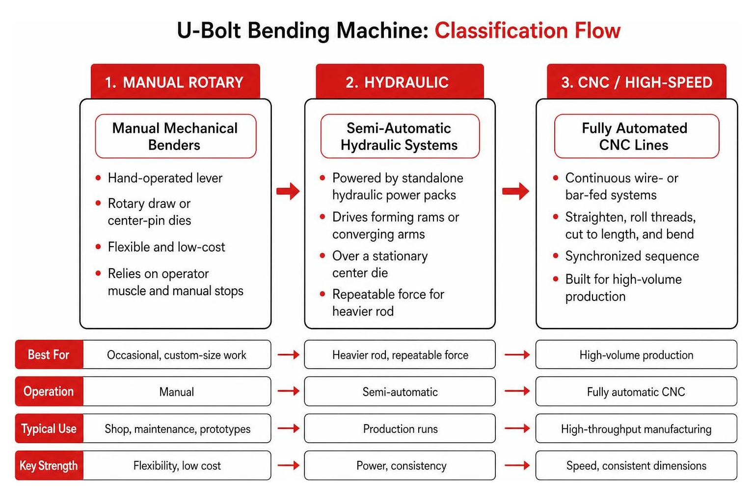
When evaluating a Custom U-Bolt Bender, equipment generally falls into three main categories:
- Manual Mechanical Benders: Hand-operated lever setups using rotary draw or center-pin dies. They are flexible and low-cost, but rely entirely on operator muscle and manual stops.
- Semi-Automatic Hydraulic Systems: Powered by standalone hydraulic power packs that drive forming rams or converging arms over a stationary center die.
- Fully Automated CNC Lines: Continuous wire- or bar-fed systems that straighten, roll threads, cut to length, and bend in a synchronized sequence.
Manual and Semi-Automatic Hydraulic Benders
Manual universal benders use rotary draw dies to form bends around a center pin. They work well for maintenance departments, repair shops, and low-volume fabricators handling custom sizes. Because manual bending relies on mechanical stops and physical leverage, consistency depends on operator technique. Forming high-strength alloys or bars thicker than 3/4 inch (19 mm) cold on a manual machine quickly becomes physically demanding.
Semi-automatic hydraulic benders bridge the gap between manual levers and multi-axis CNC machines. These units typically feature:
- Dedicated hydraulic cylinders driven by 3 HP to 5 HP electric motors operating at 1440 RPM.
- Operational hydraulic pressures reaching up to 0.8 MPa to deliver smooth, repeatable bending tonnage.
- Foot-pedal or dual palm-button actuation, allowing operators to position pre-threaded rods against stops before initiating the stroke.
- Solid, stress-relieved steel frames that eliminate machine flex under high-tonnage forming loads.
For job shops handling medium production runs of suspension U-bolts or anchor hardware up to 20 mm or 25 mm diameter, semi-automatic hydraulic units offer a dependable balance of cycle speed, forming power, and quick tooling changeovers.
Automated CNC vs. Hydraulic U Bolt Bending Machine Systems
When production requirements reach thousands of fasteners per shift, fully automated systems provide significant efficiency gains. While a standard hydraulic bender requires an operator to place each pre-cut, pre-threaded rod blank against a gauge stop, an automated system can process continuous coiled wire stock directly into finished parts.
Automated equipment, such as a Stainless Steel U-Shaped Bolt Bending Machine, integrates several manufacturing steps into a single line:
- Infeed and Straightening: Coiled wire passes through multi-roll straighteners to eliminate curvature before bending.
- Precision Cutting: High-speed shears cut blanks to exact development lengths without creating heavy burrs.
- Laser-Guided Thread Rolling: In-line rolling heads cold-form threads onto both blank ends simultaneously.
- Integrated CNC Bending: Robotic or hydraulic arms sweep the threaded blank around the center die, applying programmed overbend angles.
| Feature | Semi-Automatic Hydraulic Bender | Automated CNC Forming Line |
|---|---|---|
| Primary Infeed | Pre-cut & pre-threaded blanks | Continuous coiled wire or bar stock |
| Cycle Time | 15 to 20 seconds per part | 1 to 3 seconds per part (25–60 pcs/min) |
| Typical Shift Output | 800 to 1,200 pieces / 8-hr shift | 10,000 to 25,000+ pieces / 8-hr shift |
| Changeover Time | 5 to 15 minutes | 30 to 90 minutes |
| Ideal Application | High-mix, structural & anchor jobs | High-volume standardized fasteners |
Semi-automatic machines with 15- to 20-second cycle times produce roughly 1,200 pieces per shift. Automated machines handle standard diameters (M6 to M12) at 40 to 60 parts per minute, and heavier stock (M20 to M24) at 25 to 30 parts per minute. For custom structural fasteners, semi-automatic hydraulic units remain the standard because they accommodate rapid tooling adjustments without extended programming.
How a Modern U Bolt Bending Machine Works
A dedicated U-bolt bender forms symmetrical bends by controlling how material flows around the center die. Unlike standard rotary benders that sweep material from one side, a dedicated bender forms both legs at the same time in a single downward pass.
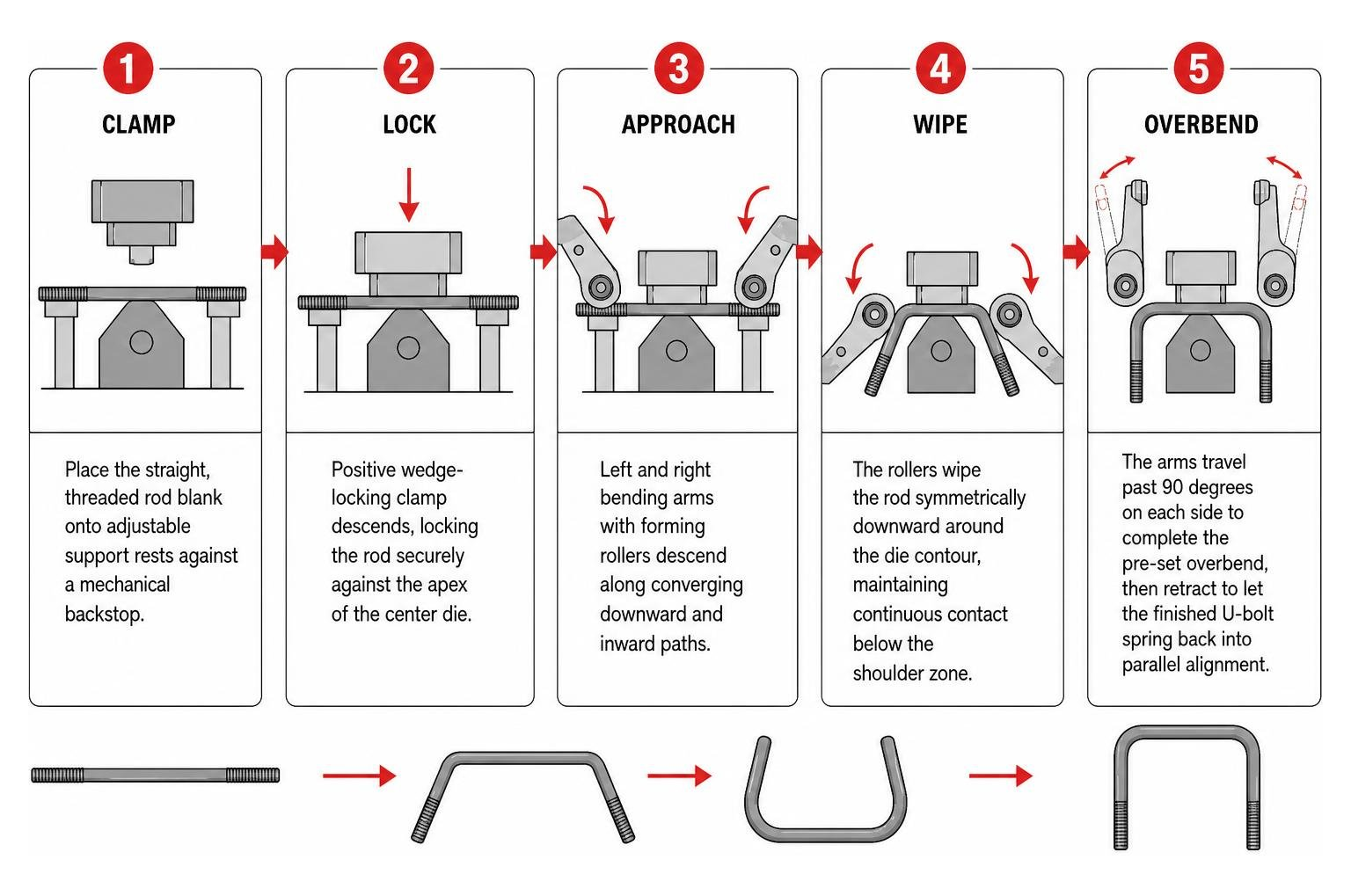
Understanding how to bend a U-bolt in 5 simple steps starts with the physical mechanics inside the forming tooling:
- The operator places the straight, threaded rod blank onto adjustable support rests against a mechanical backstop.
- A positive wedge-locking clamp descends, locking the rod securely against the apex of the center forming die.
- Left and right bending arms equipped with hardened forming rollers descend along converging downward and inward paths.
- The rollers wipe the rod symmetrically downward around the die contour, maintaining continuous contact below the shoulder zone.
- The arms travel past 90 degrees on each side to complete the pre-set overbend, then retract to let the finished U-bolt spring back into parallel alignment.
Tooling Setup and Single-Screw Calibration
Achieving parallel legs and an accurate inside width depends directly on die geometry and arm calibration. Dedicated benders often use a single-screw adjustment point that links the left and right bending arm pivot centers.
Turning this single adjustment screw moves both arm assemblies inward or outward symmetrically relative to the center die. This simultaneously calibrates:
- Forming Roller Clearance: Keeps roller-to-die spacing matching the exact bar stock diameter, preventing material pinching or loose bends.
- Overbend Calibration: Balances the terminal sweep angle across both legs so neither side finishes over- or under-bent.
- Centerline Alignment: Keeps the center die aligned with the hydraulic ram without requiring manual shimming.
For non-standard inside dimensions, custom teardrop-shaped anvils compensate for material draw. Because solid round bar pulls slightly from the back during bending, matching the anvil’s profile to the bar diameter keeps the crown flat and prevents the shoulders from necking down.
Managing Overbend, Springback, and Parallelism
Every metal alloy exhibits elastic recovery, or springback, when released from forming pressure. When bending cold carbon steel, alloy bar, or stainless stock, the legs naturally spring outward once the bending force is removed.
To maintain leg parallelism within tight tolerances (such as $\pm 0.5^\circ$), the machine must overbend the rod beyond $180^\circ$ of total included angle:
$$\text{Total Forming Angle} = 180^\circ + \theta_{\text{springback}}$$
The springback angle ($\theta_{\text{springback}}$) varies depending on the material’s yield strength, bar diameter, and the bend radius. High-strength materials like ASTM A193 Grade B7 or Grade 55 exhibit significantly more springback than mild low-carbon steel (such as ASTM A36).
Dedicated benders apply this overbend low on the straight leg rather than directly against the radius shoulder. Applying pressure low on the leg preserves the cross-sectional shape of the shoulder, prevents stress concentrations, and maintains a clean radius that seats flush against pipe saddles or mounting plates. When tightened, the U-bolt distributes clamping force evenly without distorting the threads or losing torque over time.
Dedicated Bending Machinery vs. General-Purpose Fabricators
Fabrication shops often bend U-bolts using existing equipment like press brakes or universal rotary benders instead of investing in a dedicated machine. While general-purpose tools can bend round stock, they have distinct operational trade-offs for high-volume or tight-tolerance work.
When using a step-by-step guide to bending U-bolts, comparing machine types helps clarify the tooling requirements and cycle times involved:
| Operational Parameter | Dedicated U-Bolt Bender | Press Brake with V-Die / U-Punch | Universal Manual Rotary Bender |
|---|---|---|---|
| Forming Method | Symmetrical converging wiping rollers | Dual-stage air bend or bottoming punch | Single-arm rotary draw sweep |
| Cycle Time | 15–20 seconds | 45–90 seconds (often multi-step) | 60–120 seconds |
| Leg Parallelism Control | Excellent (single-screw overbend adjustment) | Difficult (susceptible to uneven die rebound) | Fair (requires physical stop tweaking) |
| Thread Protection | High (rollers contact smooth rod below threads) | Moderate (punch/die friction can mar threads) | Low (clamping block can pinch threads) |
| Tooling Setup Time | 5 to 10 minutes | 20 to 45 minutes | 10 to 20 minutes |
| Capital Investment | Moderate | High (if purchasing machine solely for bolts) | Low |
Press brakes forming U-bolts typically use a dedicated gooseneck punch and a matching U-channel bottom die. Unless the tooling coins the bottom of the bend under high tonnage, springback can cause the legs to flare outward unpredictably.
Rotary draw benders sweep material from one side, which often draws stock unevenly. This requires the operator to offset layout center marks toward the drive pin to keep the finished leg lengths symmetrical.
Dedicated U-bolt benders eliminate these alignment issues by clamping the blank firmly on center and wiping both legs downward simultaneously.
Fastener Integrity: Rolled Threads vs. Cut Threads
When fabricating threaded fasteners that undergo cold bending, thread manufacturing method directly affects structural performance under load.
- Cut Threads: Produced by machining away steel to form thread peaks and valleys. This process interrupts the metal’s natural grain flow and creates tiny surface stress risers along the root of each thread.
- Rolled Threads: Formed by squeezing the rod blank between hardened dies under high pressure. The steel grain flows smoothly over the crests and roots, work-hardening the root zone and increasing fatigue resistance by up to 30%.
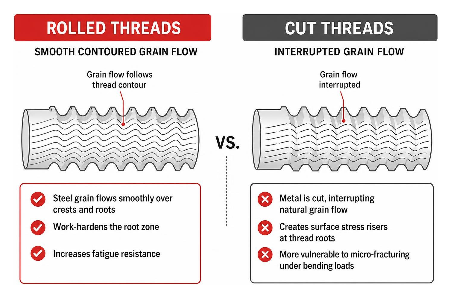
When high-tonnage bending arms engage a pre-threaded rod, cut threads are more vulnerable to micro-fracturing along their roots if tooling makes contact with the threaded section.
Using pre-threaded rods with rolled threads protects fastener integrity under high clamping loads, such as in heavy-duty pipeline U-bolt clamps. Dedicated benders position their forming rollers to contact only the unthreaded body of the rod, keeping the threads intact and dimensionally accurate for smooth nut engagement.
Critical Factors When Selecting Industrial Bending Equipment
Selecting industrial bending machinery requires matching equipment specifications to your current rod inventory, material grades, and daily production schedules.
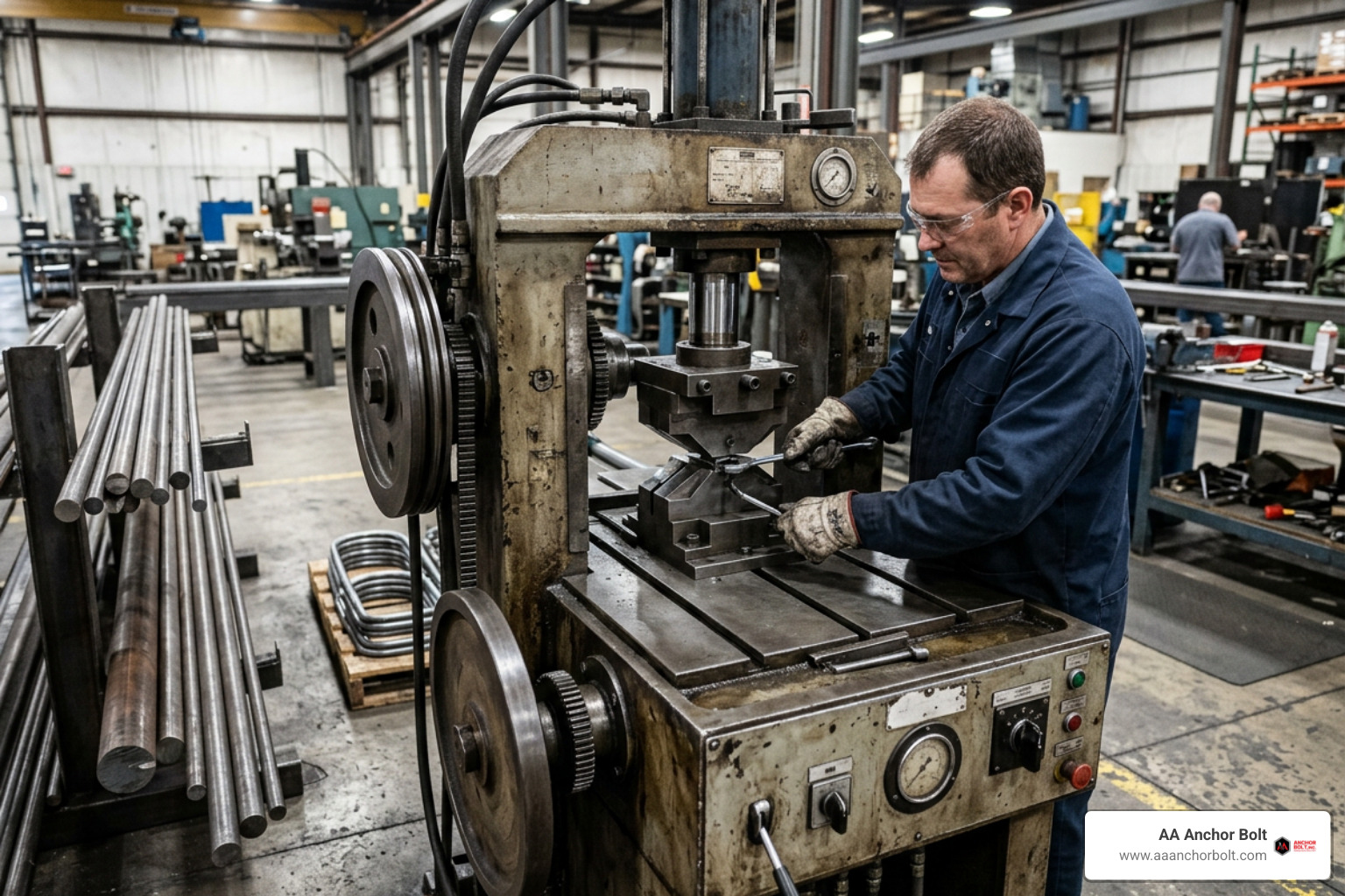
When we evaluate equipment for our own domestic manufacturing capabilities, we look closely at frame construction and hydraulic stability. High-tonnage bending places continuous outward thrust on machine frames; any structural deflection leads directly to flared, out-of-parallel bolt legs.
Prioritize machines built with stress-relieved, fully welded heavy steel plate frames. Stress relief prevents the machine structure from warping after years of continuous high-tonnage cycling.
Key machine safety and maintenance features to check include:
- Dual Anti-Tie-Down Palm Buttons: Keeps the operator’s hands safely outside the die zone during the downstroke.
- Integrated Safety Light Curtains: Instantly halts hydraulic ram movement if an operator reaches into the forming area.
- Hydraulic Pressure Relief Valves: Protects the cylinder, motor, and tooling from structural overload if oversized stock is loaded by mistake.
- Centralized Lubrication Ports: Simplifies regular grease maintenance on main pivot bushings and roller guide slides.
Key Specifications to Evaluate in a U Bolt Bending Machine
Before committing to a machine platform, review its baseline technical specifications against your project requirements:
- Bar Stock Diameter Capacity: Standard industrial hydraulic units handle solid round bar from 15 mm (approx. 5/8 in) up to 32 mm (approx. 1-1/4 in). Make sure the maximum tonnage matches your highest-strength materials (e.g., ASTM A193 B7 or 4140 alloy steel).
- Maximum Blank Length: Check that the machine frame and backstop allow sufficient clearance for your longest required blank lengths (often up to 1000 mm / 40 in or longer for structural piping).
- Bending Angular Accuracy: Precision production machinery should hold an angular tolerance within $\pm 0.5^\circ$, ensuring both legs drop cleanly through drilled mounting plates without field adjustment.
- Power and Electrical Ratings: Industrial hydraulic power units generally require 3-phase electrical drops (230V/460V or 380V/440V) running 3 HP to 15 HP pump motors, depending on cylinder bore and cycle speed.
- Overall Footprint and Machine Weight: Heavy hydraulic benders weigh between 2,000 lbs (900 kg) and 12,000+ lbs (5,500 kg). Ensure your facility’s concrete pad can support the static weight and dynamic cycle loads without anchoring shift.
Total Cost of Ownership and Production Volume Requirements
A machine’s purchase price represents only part of its total operating cost over time. Evaluating the full cost of ownership helps ensure your equipment choice aligns with actual production volume.
- Capital Investment (CapEx): Manual benders range from under $1,000 for basic lever tools to roughly $5,000 for heavy-duty universal units. Semi-automatic hydraulic machines typically run between $8,000 and $30,000+ depending on tonnage and controls. Fully automated CNC cut, thread, and bend lines can range from $50,000 to well over $150,000.
- Tooling and Die Maintenance: Factor in the cost of interchangeable center anvils and roller sets for each pipe nominal size and rod diameter you run. Hardened tool steel dies (such as D2 or heat-treated 4140) last longer and help prevent surface galling when bending stainless steel.
- Changeover Efficiency: For low-volume, high-mix custom manufacturing, changeover speed is often more important than raw cycle time. A hydraulic machine with a single-screw adjustment can change bolt sizes in under 10 minutes, saving valuable labor on short production runs.
Frequently Asked Questions About U-Bolt Bending
How do U-bolt bending machines prevent leg spread and maintain parallelism?
Dedicated machines maintain parallel legs by pairing controlled overbending with positive die lockdown.
During the stroke, a center wedge clamp locks the rod against the apex of the forming die to keep the blank from lifting or shifting. Symmetrical forming rollers then wipe downward and inward on converging paths, bending both legs past $90^\circ$ to compensate for the material’s elastic springback.
When the forming rollers retract, the rod legs relax into parallel alignment ($\pm 0.5^\circ$).
What cycle times and production rates can industrial benders achieve?
Cycle times and production rates depend primarily on the machine’s automation level:
- Semi-Automatic Hydraulic Benders: Complete a single bend stroke in 15 to 20 seconds. An operator loading and unloading pre-cut blanks can produce approximately 150 to 200 parts per hour, or roughly 1,200 pieces per standard 8-hour shift.
- Fully Automated CNC Lines: Integrate straighteners, thread rollers, and synchronized bending arms to produce 25 to 60 finished parts per minute, yielding 10,000 to 25,000+ completed fasteners per shift.
Can pre-threaded rods be bent without damaging the threads?
Yes. Pre-threaded rods can be cold-bent without thread damage by using properly designed tooling and clean machine geometry:
- Tooling Contact Area: Forming rollers should contact only the unthreaded center body of the rod blank, keeping direct rolling friction away from the threaded ends.
- Smooth, Hardened Rollers: Roller assemblies made from hardened, polished tool steel turn freely during the stroke, eliminating sliding friction against the workpiece.
- Rolled Thread Structure: Using pre-threaded rod with rolled threads rather than cut threads provides a smoother surface and higher fatigue resistance throughout the forming process.
Conclusion
Choosing the right U-bolt bending equipment comes down to balancing bar diameter capacity, daily production volume, and dimensional tolerance control. While manual universal benders handle sporadic job-shop repairs, dedicated semi-automatic hydraulic benders provide the repeatable clamping force, springback control, and rapid changeover times needed for industrial structural fasteners.
For high-volume standardized production, automated CNC lines combine straightening, threading, and forming into a single process.
When project schedules require immediate delivery without capital equipment investments, working with an established domestic manufacturer keeps your jobs moving forward.
At AA Anchor Bolt, our Michigan facility maintains nearly a million pounds of prime domestic steel bar stock and full in-house production control. We provide fast turnarounds on standard and custom high-strength fastener products, manufactured to strict tolerances for critical infrastructure, structural steel, and industrial piping applications.