Get Bent! A Step-by-Step Guide to Bending U-Bolts
Bending U-Bolts Starts With Accurate Forming
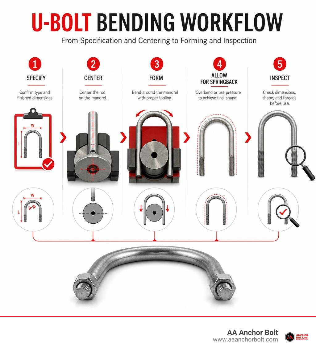
Bending U-bolts means cold-forming a straight steel rod around a correctly sized mandrel so both threaded legs are even and the inside shape fits the pipe, axle, frame, or mounting point.
For a fast, reliable result:
- Confirm the bend type and finished dimensions before setup.
- Center the rod exactly on the mandrel.
- Use tooling sized for the rod diameter, bend radius, and material grade.
- Allow for springback by overbending or using coining pressure where needed.
- Check leg length, inside width, bend shape, and threads before installation.
A U-bolt can look simple, but small errors can make it unusable. An off-center rod produces unequal legs. A die that is too large changes the fit. High-tensile or stainless material may spring back more than mild steel. For contractors on a tight schedule, accurate setup is what prevents scrap, rework, and field delays.
I am Pauline Horton, and next we will cover the measurements and bend profiles to define before any rod goes into the bender.
Related content about bending u bolts:
Key Specifications and Measurement Standards Before Bending
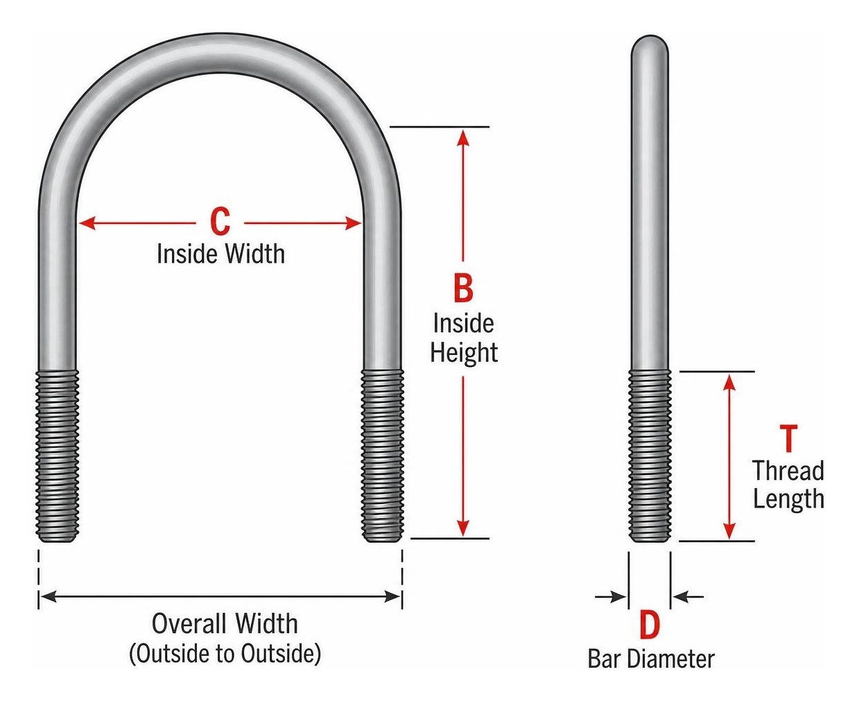
Before taking stock rod to the shop bender, you must know the exact geometric parameters of your finished fastener. Misinterpreting callouts is one of the easiest ways to turn expensive pre-threaded rod into scrap metal. A complete specification for bending u bolts requires five essential measurements:
- Inside Width (C): The physical space between the two parallel legs. For pipe supports, this must accommodate the pipe’s actual outside diameter plus any insulation, protective sleeves, or coatings—nominal pipe size is not actual clearance!
- Inside Height (B): The distance measured from the top crown radius (inside curve) down to the bottom face of the legs.
- Leg Length: The overall length of each straight leg from the top of the bend down to the leg tip.
- Thread Length (T): The amount of rolled or cut thread on the bottom of each leg required for nuts and backing plates.
- Bar Diameter (D): The thickness of the raw rod stock, typically ranging from 3/8 inch up to 1 1/2 inches (M6 to M24).
For comprehensive dimensioning standards, check out the detailed U-Bolt Guide: Bend Types, Sizes & Applications.
Square, Round, Semi-Round, and V-Bend Profiles
The geometry of the bending mandrel dictates the final shape of the U-bolt. Choosing the wrong mandrel profile creates point-loading stresses that cause joint failure down the line:
- Round Bend: The classic semi-circular arch. Perfect for securing smooth, cylindrical objects like round pipe networks, structural tubing, or smooth vehicle axles.
- Square Bend: Features 90-degree crisp corners and a flat top crown. Tailor-made for square box-tube frames, mounting plates, channel iron, or rectangular trailer axles.
- Semi-Round Bend: Features a flattened upper crown with angled transitions down to vertical legs. Often called “elbow” or corner-radius bends, they balance clearance in tight mounting brackets.
- V-Bend: Features angled sides meeting at a central point, centering round conduit or piping into fixed structural notches.
When setting up your bender, always match the inner radius die directly to the workpiece profile. To dive deeper into execution, read our guide on How to Bend a U-Bolt in 5 Simple Steps.
Material Grades and Their Impact on Formability
Material selection governs both load-bearing capacity and the mechanical force needed when bending u bolts. Carbon and alloy steels require different bending strategies than stainless grades:
- Grade 4.6 Mild Steel: Tensile strength of roughly 400 MPa. Soft and forgiving, this stock cold-bends easily with minimal force and exhibits low springback, making it ideal for general-purpose structural mounts.
- Grade 8.8 High-Tensile Carbon Steel: Heat-treated alloy steel featuring an 800 MPa tensile strength. Standard for automotive leaf springs and heavy equipment mounting. Requires substantially higher bending hydraulic tonnage and carefully calibrated springback compensation.
- A2-70 (304 Stainless Steel): Provides 700 MPa tensile strength. Excellent atmospheric corrosion resistance, but work-hardens rapidly during cold forming.
- A4-80 (316 Marine Grade Stainless Steel): Delivering 800 MPa tensile strength, A4-80 is built for severe chemical and marine environments. Bending A4-80 requires high-tonnage tooling and specialized mandrels to overcome significant material rebound.
Selecting the wrong grade can lead to unexpected structural failure or snapped tooling during forming. Read more about structural choices in Choosing the Right U-Bolts.
Bending U-Bolts: Essential Methods, Tooling, and Machinery Options
Achieving clean, uniform U-bolts requires choosing the right machinery for your production volume. Job shops making low-volume custom runs use different tooling than automated fastener production lines.
| Equipment Type | Pros | Cons | Best Application |
|---|---|---|---|
| Manual Universal Bender (e.g., Hossfeld / Rotary) | Low setup cost, versatile teardrop dies, handles up to 1″ rod cold. | Manual effort required, relies on operator measuring accuracy. | Short runs, maintenance shops, custom repair parts. |
| Hydraulic U-Bolt Press (Dedicated UB-302 / UB-502) | Rapid cycle time, integrated centering devices, consistent bends. | Higher equipment cost, requires dedicated mandrel tooling sets. | Medium to high-volume manufacturing, suspension shops. |
| Automated CNC Rotary Bender | Programmable springback compensation, precise leg symmetry, zero setup changeover. | High capital investment ($10,000–$50,000+). | Production lines, large-scale OEM fastener fabrication. |
Step-by-Step Bending U-Bolts with Hydraulic and Manual Benders
When bending u bolts in small batches or custom production runs, follow this practical shop floor procedure:
- Select and Set the Mandrel: Mount the central mandrel (forming post) matching your required inside width and profile (round, square, or semi-round) into the machine frame.
- Install Grooved Rollers: Choose forming arms equipped with grooved roller dies sized precisely to your rod stock diameter (e.g., 5/8″ or 3/4″). Plain flat rollers can flatten the rod profile or mar pre-cut threads.
- Position and Center the Bar: Lay the pre-threaded steel rod symmetrically across the mandrel face. Ensure the exact midpoint of the rod aligns with the center axis of the mandrel.
- Engage the Bend Cycle: Actuate the hydraulic press cylinder or swing the manual bender arms. The grooved side rollers will sweep around the central mandrel, cold-forming the rod evenly along both sides.
- Coin the Crown: At full stroke stroke-completion, apply maximum hydraulic pressure against the mandrel face to “coin” the bend zone, setting the metal grain structure.
- Retract and Inspect: Release pressure, unload the formed U-bolt, and verify inside leg spacing, height, and alignment with a dedicated gauge plate.

Threading Integrity: Rolled Threads vs Cut Threads
A major decision point when bending u bolts is whether threads are applied before or after forming, and how they are generated.
- Rolled Threads: Produced by cold-extruding unheated metal between hardened thread dies. Roll-threading requires an undersized blank bar (for instance, approximately 7.1 mm bar stock for an M8 thread). The process reshapes the steel grain structure rather than cutting across it, providing superior fatigue resistance for high-stress applications like suspension leaf springs or high-vibration structural joints.
- Cut Threads: Produced by lathe or die-cutting away steel from a full-sized bar diameter. Cut threads create micro-sharp stress risers at the root of the thread pitch and cut across metal grains, reducing dynamic strength.
In commercial manufacturing, high-strength U-bolts are cold-bent from pre-threaded rolled stock. Grooved forming rollers protect the pre-rolled threads from physical distortion during the bend cycle. To understand thread performance across industrial applications, consult our Ultimate Buyer’s Guide to Pipeline U-Bolt Clamps.
How to Ensure Precision: Centering and Springback Compensation
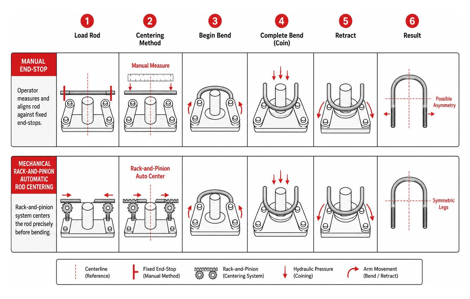
The primary challenge in custom U-bolt bending is leg symmetry and dimensional stability. If a steel bar is off-center by even 1/8 inch prior to forming, the finished part will feature mismatched leg lengths. Because cold-bent U-bolts cannot easily be unbent or straightened without damaging the steel, asymmetrical parts almost always end up in the scrap hopper.
Compensating for Springback When Bending U-Bolts
Every metal exhibits elastic recovery—known as springback or rebound—when released from a bending die. When bending cold carbon or stainless steel, the metal legs naturally flare outward, expanding the inside width past the intended spec.
To defeat springback, fabricators rely on three practical techniques:
- Undersized Mandrels & Overbending: Use a forming die slightly narrower than the target inside width (or bend 2 to 4 degrees past 90/180 degrees) so the legs rebound right into parallel tolerance.
- Coining the Bend: Squeeze the rod firmly at the apex of the bend between matching male and female dies under high hydraulic tonnage. Coining plasticizes the metal at the bend heel, eliminating internal elastic tension.
- Tapping the Heel: If a finished U-bolt springs back too tight (legs squeezed inward), place the outside crown (“heel”) flat against an anvil and strike it sharply with a hammer. Striking the outer heel causes the legs to open up without requiring manual prying.
Automatic Centering Mechanisms and Mandrel Alignment
To eliminate visual guesswork, ink marking, or manual tape-measure alignment, professional bending machines (like the Vic Roc UB-302 or UB-502 series) utilize specialized automatic centering mechanisms.
These centering devices feature a conjoint mechanical carriage linked via a central rack-and-pinion assembly. Two opposed sliding end plates move symmetrically toward or away from the central mandrel. When an operator places a pre-threaded rod into the fixture and closes the centering arms, both end plates collapse inward at equal speeds, locking the exact midpoint of the rod over the mandrel centerline regardless of total rod length.
Spring-loaded mounting brackets allow the centering plates to pivot downward safely as the bending arms push the rod legs through their forming arc.
Critical Post-Bending Installation, Torque Specs, and Common Pitfalls
Fabricating a perfect U-bolt is only half the battle; proper field installation prevents joint failure. Automotive leaf springs and heavy structural pipe supports represent two critical areas where improper installation can lead to severe equipment damage.
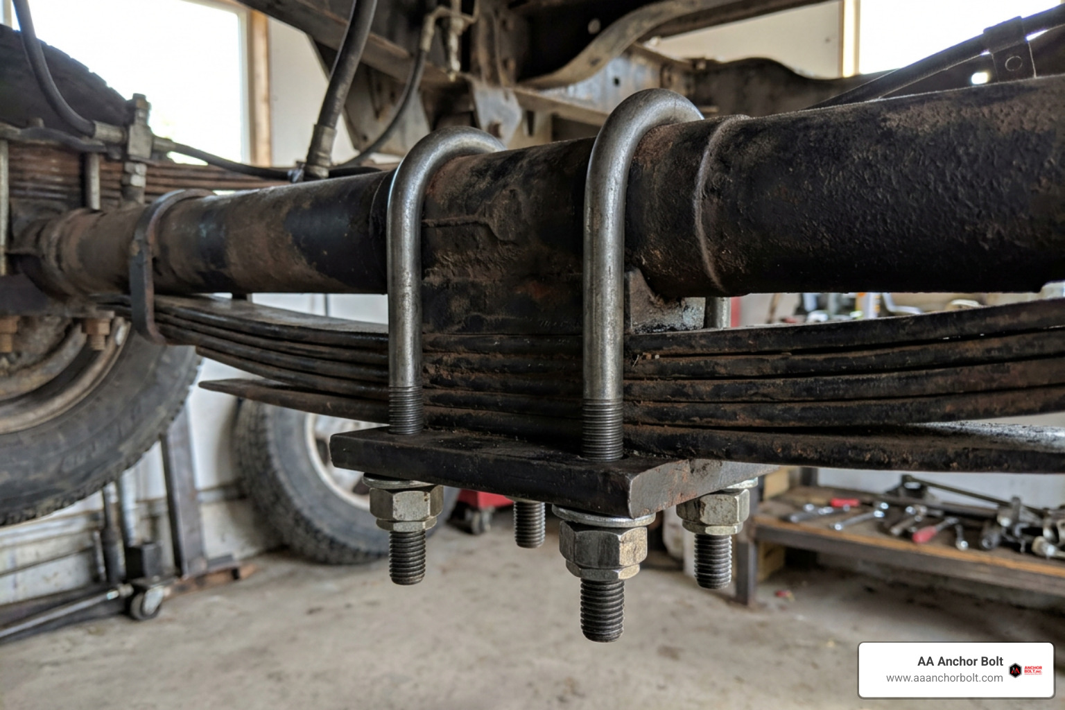
For suspension applications, suspension manufacturers exclusively use Grade 8.8 high-tensile steel U-bolts. Proper tightening requires a calibrated torque wrench, following a diagonal cross-pattern in incremental stages:
- M14 (9/16″): 110 to 130 Nm (80–95 ft-lb)
- M16 (5/8″): 140 to 180 Nm (100–130 ft-lb)
- M18 (11/16″): 180 to 220 Nm (130–160 ft-lb)
- M20 (3/4″): 220 to 270 Nm (160–200 ft-lb)
In structural piping, ASME B31.3 regulations require non-gripped sliding pipe guides to maintain a 1.5 mm to 2.0 mm clearance gap at the top crown radius. Over-tightening non-gripped U-bolts converts a free-sliding guide into an accidental rigid anchor, causing structural pipe wall buckling during thermal expansion. For full installation codes, refer to the Ultimate Guide to U-Bolt Pipe Support and review purchasing criteria in our U-Bolt Buying Guide.
Common Bending Mistakes and Diagnostic Troubleshooting
When troubleshooting problematic U-bolts on the shop floor, use this diagnostic reference:
- Unequal Leg Lengths: Caused by poor centering on the mandrel face or slipping forming rollers. Fix: Implement mechanical end-stops or a rack-and-pinion centering fixture.
- Flared or Out-of-Parallel Legs: Caused by uncompensated material springback. Fix: Use an undersized mandrel die or increase hydraulic coining pressure at the end of the stroke.
- Cracked Outer Bend Crown: Caused by cold bending around a mandrel radius that is too tight, or attempting to cold-bend unannealed high-tensile bar. Fix: Increase bend radius die size or pre-heat the bend area.
- Crushed or Stripped Threads: Caused by using flat bending rollers over pre-threaded legs. Fix: Switch to grooved rollers matching thread outer diameter.
- Galvanic Corrosion at Contact Points: Occurs when bare steel U-bolts directly contact stainless steel piping. Fix: Install thermoplastic liners or PTFE isolation pads between the bolt and pipe.
Frequently Asked Questions About Bending U-Bolts
Can you adjust U-bolt legs after bending if they are too narrow?
Yes! If the legs sit too close together after bending, you don’t need to pry them apart with force. Place the outside heel (the outer center crown of the bend) firmly against a metal anvil and tap it with a hammer. Striking the outside heel expands the leg spacing evenly.
Should threads be rolled before or after bending U-bolts?
In commercial production, threads are almost always rolled onto straight bar stock before bending. Pre-threading is significantly faster, reduces thread tool wear, and ensures uniform pitch. Grooved bending rollers protect the threads from damage during the forming pass.
Why should leaf spring U-bolts never be reused after disassembly?
Leaf spring U-bolts are subjected to intense mechanical stress and stretch slightly (entering plastic deformation) when torqued to specification. Reusing a stretched U-bolt prevents it from holding correct clamping torque, risking thread stripping, vehicle axle shift, or fatigue failure under load.
Conclusion
Mastering bending u bolts requires combining accurate pre-bend geometry, proper material grade selection, and calibrated springback compensation. Whether you are forming mild steel pipe hangers or high-tensile leaf spring bolts, precise centering on the mandrel is what separates quality fasteners from unusable scrap metal.
At AA Anchor Bolt, we take pride in manufacturing premium custom fasteners right here in Northville, Michigan. With nearly a million pounds of domestic steel ready in house, our team delivers ultra-fast turnarounds on custom anchor bolts, U-bolts, and specialized construction hardware tailored directly to your project specifications.
Need custom fasteners built to exact standards? Read our specialized guide on U-Bolt for Data or visit Explore Custom Anchor Bolts and Fasteners to request a fast quote on your next order!